If you would like to read the other parts in this article series please go to:
- Installing, Configuring and Testing an Exchange 2007 Cluster Continuous Replication (CCR) Based Mailbox Server (Part 2)
- Installing, Configuring and Testing an Exchange 2007 Cluster Continuous Replication (CCR) Based Mailbox Server (Part 3)
Introduction
Exchange Server 2007 introduces several new high availability features, one of them is the Cluster Continuous Replication (CCR) feature. This feature takes the new Exchange Server 2007 Log file shipping and replay features and combines them with the features that are available in a more traditional 2 node Windows 2003 active/passive cluster setup. A traditional 2 node active/passive cluster certainly has its benefits, but it also has one major drawback and that is you still have a single point of failure when it comes to Exchange databases.
Prerequisites
In order to follow the steps throughout this article series, you need the following:
-
A Windows 2003 Active Directory forest with at least one Domain Controller (raised to 2000 or 2003 forest functional level).
-
Two Windows 2003 Server R2 Enterprise Editions or Windows 2003 Server SP1 Enterprise Editions.
-
One Windows File share Witness (MS recommends this to be an Exchange 2007 Hub Transport Server in the existing Exchange 2007 organization)
Note
Remember to apply the update mentioned in MS KB article 921181 to both servers that will act as nodes in the Exchange Server 2007 Clustered Mailbox setup. The update adds a new file share witness feature to the current Majority Node Set (MNS) quorum model. The file share witness feature lets you use a file share that is external to the cluster as an additional “vote” to determine the status of the cluster in a two-node MNS quorum cluster deployment, which is a requirement in order to make use of the cluster continuous replication (or CCR in short) functionality in Exchange Server 2007.
In addition to the above prerequisites you should be aware of the following general requirements as well:
-
When dealing with CCR environments you must use/can only use one database per storage group.
-
You cannot create a public folder database in a CCR environment if you already have more than one public folder database in your organization.
- You can create up to 50 storage groups and 50 databases on a CCR cluster. Bear in mind though, that you should create only one database per storage group.
- The cluster in which Exchange 2007 is installed cannot contain Exchange Server 200x, or any version of Microsoft SQL Server. Running Exchange 2007 in a cluster with any of these other applications is not supported.
Warning
Since Exchange Server 2007 Beta 2 isn’t supported in a production environment, unless you’re participating in the Rapid Deployment Program (RDP) or Technology Adopter Program (TAP), you should install the mailbox cluster in a test domain.
Configuring the Network Settings for the Cluster nodes
When you start the servers that are to be the nodes in the cluster, start by naming the machines E2K7Node1 and E2K7Node2 or whatever naming scheme you want to use (these names have nothing to do with the Exchange server name which your clients will be configured to connect to later on). Now name the two network connections Public and Private for the external and the internal network respectively (remember to do this on both nodes).

Figure 1: Network Connections
Click Advanced > Advanced Settings, if it’s not already the case, make sure Public is listed first on the binding order list, then Private and lastly Remote Access Connections.

Figure 2: Binding order
Before Exchange 2007 SP1 released, it was also recommended to disable File and Printer Sharing for Microsoft Networks for the private network as shown in Figure 3. However, when SP1 released this guidance changed, since Exchange 2007 SP1 introduced a new cmdlet named Enable-ContinuousReplicationHostName. This cmdlet makes it possible to specify over which network log files should be ship and seeded. So no matter whether you deploy CCR on Windows 2003 or Windows 2008 based servers, please don’t disable File and Printer Sharing for Microsoft Networks for the private network.

Figure 3: Disabling File and Printer Sharing for Microsoft Networks
Configure the Public network with the respective network settings you use in your test environment.

Figure 4: Configuring the Public network
Configure the Private network with an IP address and a subnet mask. Nothing else is required since this network is only used for communication (heartbeats) between the nodes in the cluster.

Figure 5: Configuring the Private network
Now click Advanced then select the DNS tab. Here you should untick both Register this connection’s addresses in DNS and Use this connection’s DNS suffix.

Figure 6: Configuring DNS settings for the Private network
Click the WINS tab. Untick Enable LMHOSTS lookup and select Disable NetBIOS over TCP/IP.
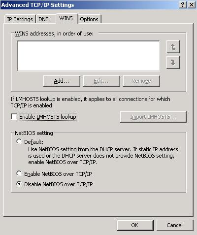
Figure 7: Configuring WINS settings for the Private network
Click OK three times and close the network connections window.
Now add both Windows 2003 Servers as member servers in your Active Directory test domain.
Creating and Configuring the Windows 2003 Server Cluster
Now that the two servers are ready to act as nodes in a Windows 2003 cluster, it’s time to create the actual Windows 2003 Server Cluster. In order to do so logon to E2K7Node1 with a Domain admin account, then click Start > Administrative Tools > Cluster Administrator, and select Create new cluster in the drop-down box. Now click OK.

Figure 8: Creating a new cluster
Note
You can also open a command prompt and type Cluster.exe /create /wizard in order to start the cluster wizard.
Click Next.
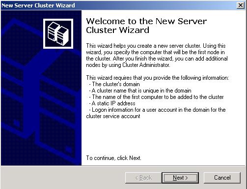
Figure 9: Cluster Wizard
Specify the domain name as well as the cluster name (name for the Windows 2003 cluster NOT the Exchange cluster name which the clients will connect to), then click Next.
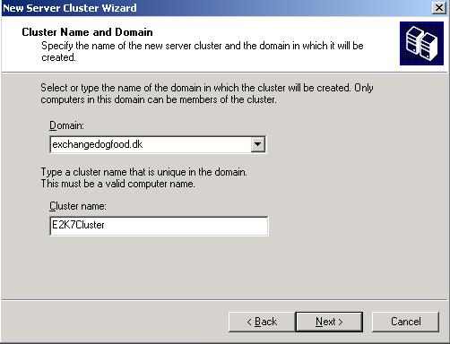
Figure 10: Cluster Name and Domain
Type the name of the Windows 2003 server that is to be the first node in the cluster, in this case E2K7Node1, then click Next.

Figure 11: Adding the First Cluster Node
Let the cluster wizard determine the cluster configuration and click Next.
Note
You can ignore the two warnings in Figure 12, since the nodes in a cluster continuous replication based mailbox server setup aren’t going to share the same disk subsystem.
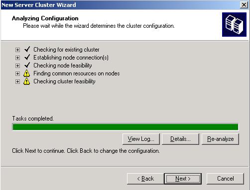
Figure 12: Analyzing Cluster Configuration
Now enter the IP address that the cluster management tools should use to connect to the cluster, in this case 10.10.1.216, then click Next.
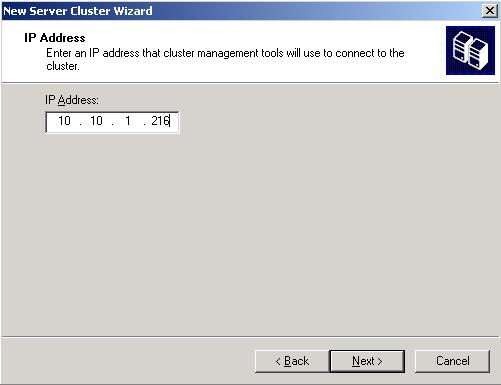
Figure 13: Specifying the IP address the Cluster Management Tools should connect to
Enter the credentials of the cluster service account (When speaking test environments I’m often too lazy to create a specific cluster service account and instead tend to use the Administrator account which will have the appropriate permissions) and click Next.

Figure 14: Entering the credentials of the Cluster Service Account
Now click Quorum and select Majority Node Set as the resource type, then click Ok and Next.

Figure 15: Proposed Cluster Configuration

Figure 16: Setting Majority Node Set as the Resource Type
Now wait for the cluster to be configured, then click Next.

Figure 17: Creating the Cluster
When the cluster has been completed successfully you can click Finish.

Figure 18: Cluster Wizard Successfully Completed
We now have a full working Windows 2003 cluster running, but since there’s only one node it’s not very fault tolerant. So let’s add the second Windows 2003 server too. We can do this by right-clicking E2K7Node1 in the left pane of the Cluster Administrator, then selecting New > Node as shown in Figure 19 below.

Figure 19: Adding a second node to the Cluster
The Add Nodes Wizard will launch and you can click Next.

Figure 20: Add Nodes Wizard
Enter the name of the server that is going to be the second node (in this case E2K7Node2), then click Next.

Figure 21: Entering the name of the second node
Again let the Add Notes Wizard determine the cluster configuration, then click Next.

Figure 22: Analyzing Cluster Configuration
Enter the password for the cluster service account (in this case the Administrator account), then click Next.

Figure 23: Entering the password for the Cluster Service Account
When you are verified, you want to add the second node to the cluster with the configuration shown in Figure 24, click Next.

Figure 24: Proposed Cluster Configuration for node 2
When the cluster has been configured properly without any errors or warnings, click Next.

Figure 25: Cluster is configured for the second node
When the Add Notes Wizard has completed successfully, click Finish.

Figure 26: Completing the Add Nodes Wizard
The second Windows server is now part of the cluster as can be seen in Figure 27 below.

Figure 27: Cluster Administrator with two nodes
Alright we have reached the end of part one, but you can look forward to part two of this article series in the near future. Until then have a nice one!
If you would like to read the other parts in this article series please go to:
- Installing, Configuring and Testing an Exchange 2007 Cluster Continuous Replication (CCR) Based Mailbox Server (Part 2)
- Installing, Configuring and Testing an Exchange 2007 Cluster Continuous Replication (CCR) Based Mailbox Server (Part 3)