If you would like to read the other parts in this article series please go to:

Introduction
We continue this week with part 4 of my series on the new features included with the Beta 2 of the TMG firewall. I thought that this would be the last article in the series, but then I realized that there was too much going on in the Networking Node in the TMG firewall console to fit anything else into the article this week. So we will confine our attention to the Networking Node this week and see if we can finish up the series next week.
The Networking Node
Let us take a look at the Networking Node in the left pane of the console. If it is not already open, open up the TMG firewall console, expand the server name and then click on the Networking node. In the middle pane of the console, you will see the following tabs:
- Networks
- Networks Sets
- Network Rules
- Network Adapters
- Routing
- Web Chaining
- ISP Redundancy
Some of these we have seen in previous versions of the firewall, but some of them are new. I will call out the new ones, new features and capabilities as we look at each one in more detail.
The Networks Tab
The Networks tab was seen in previous versions of the firewall and includes all the networks defined on this firewall or firewall array. The default TMG Firewall Networks include:
- External
- Internal
- Local Host
- Quarantined VPN Clients
- VPN Clients
These are the same default Networks seen in previous versions of the firewall, so not much new happening here. When you double click on one of the Networks, you will see a Properties dialog box similar to what you saw in previous versions of the firewall. However, one thing that is different is that you will see options for CARP and NLB. Since there is no Standard and Enterprise edition available for the Beta 2, it is not clear if these features will be available in all versions of the RTM TMG firewall. In fact, it is not clear if there will be different versions by the time the product is released.
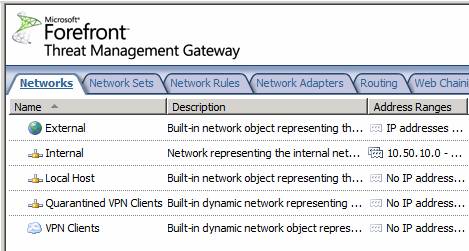
Figure 1
The Network Sets Tab
The Network Sets tab includes the groups of TMG Firewall Networks that comprise the default TMG Network Sets. The default Network Sets are:
- All Networks (and Local Host)
- All Protected Networks
- Forefront codename Stirling Monitored Networks
If you are an experienced ISA firewall admin, you probably noticed the new Network Set, the Forefront codename Stirling Monitored Networks set. The description of this network is; “This predefined network set includes the networks monitored by Forefront codename Stirling” – nice tautological description, eh?
I checked the Help file and unfortunately there is no mention of the Stirling Network Set. I am looking forward to some guidance in this area in the future, but by then, Stirling will probably have a product name and the name of this Network Set will change.

Figure 2
The Network Rules Tab
Click on the Network Rules tab and you will see the default Network Rules. The default Network Rules defined on the Beta 2 of the TMG firewall include:
- Local Host Access
- VPN Clients to Internal
- Internet Access
This is pretty much what we saw in previous versions of the firewall. But there are some big changes in this area. Double click on the Internet Access Network Rule to see where those changes lie.

Figure 3
In the Properties dialog box for the default Internal Network, you can see a new tab, NAT Address Selection. The NAT Address Selection tab allows you to choose what IP address on the external interface is used as the source IP address for connections that trigger the Network Rule. This is a feature we have been hoping to see for a long time, and this is a great first step in the right direction. No, it is not the “static NAT” feature that a lot of ISA firewall admins were looking for, but it solves some problems that we have had in the past, where we were limited to always using the default IP address on the external interface as the source IP address for all outbound connections.

Figure 4
Let us now take a look at this feature in a little more detail. In the right pane of the TMG firewall console, click the Create a New Network Rule link. This brings up the Welcome to the New Network Rule Wizard page. We will enter a name in the Network rule name text box, in this case we will name it Mail-1, representing an outbound mail server on our internal network. Click Next.

Figure 5
On the Network Traffic Sources page, click the Add button and in the Add Network Entities dialog box, select the Mail Server 1 Computer Object that was created earlier.

Figure 6
The Mail Server 1 Computer Object appears in as a source on the Network Traffic Sources page. Click Next.

Figure 7
On the Network Traffic Destinations page we select the destination for this Network Rule. In this case, we want to set the destination as the default External Network, so we click Add and then select External in the Add Network Entities dialog box.

Figure 8
The default External Network appears in the Network Traffic Destinations page. Click Next.

Figure 9
On the Network Relationship page, select the Network Address Translation (NAT) option and click Next.

Figure 10
The NAT Address Selection page is new. Here you can choose from the following:
- Always use the default IP address – this option will set the source IP address of the outbound connection to be the default IP address on the external interface of the firewall. This is the same behavior seen in previous versions of the firewall
- Use the selected IP address – this option allows you to choose an IP address on the external interface of the firewall that will be presented as the source IP address based on the source and destination set for this rule.
- Use selected IP addresses for each network – this option can be used when you have multiple NICs on the firewall, or when you have multiple members of a firewall array and you are not using NLB. This option allows you to choose specific IP addresses on each NIC, so that all outbound connections, through all potential interfaces, have a source IP address that you can control.
In this example we will select the Use the selected IP address option and select the IP address 192.168.1.175, and click Next.

Figure 11
On the Completing the New Network Rule Wizard page, review the settings and click Finish. Then click Apply at the top of the middle pane of the console to save the changes.

Figure 12
At this point you can see the new Network Rule in the middle pane of the console, and a new column for this rule, the NAT Addresses column. This lets you know what the source IP address will be for outbound connections that trigger this rule.
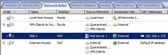
Figure 13
The Network Adapters Tab
The Network Adapters tab is an entirely new tab, not seen in previous versions of the firewall. The Tasks tab for the Network Adapters tab appears in the figure below. Here you can manipulate some of the NIC settings from within the TMG firewall console.

Figure 14
In the middle pane of the console you see a list of NICs installed on this TMG firewall computer. Columns include:
- Name – the name assigned to the NIC
- Type – whether the NIC uses Static or DHCP addressing (dynamic)
- IP Addresses – the IP address or addresses assigned to the NIC
- Subnets – the subnet mask or masks (if IP addresses from different network IDs are assigned to the NIC)
- Status – either connected or disconnected
That’s some handy information that you had to go somewhere else to find in the past.

Figure 15
But wait! There is more. Double click on one of the NICs and you will see a Properties dialog box that allows you to do a few more things. Here you can configure the NIC to use static or dynamic addressing. This includes IP addressing, subnet mask, default gateway, and DNS servers.
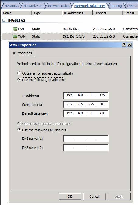
Figure 16
The Routing Tab
This is another new tab not seen in previous versions of the firewall. On the Routing tab you can see the routing table entries on the TMG firewall computer. This is pretty handy, as missing routing table entries are a major offender in many ISA and TMG firewall troubleshooting scenarios.
There is a curious link on in the Tasks tab in the Task Pane. The link is Create an Array Topology Route. Wow! That sounds really cool. An Array Topology Route. I wonder what that is? I clicked the link and it brought up the Array Topology Route dialog box. It looks like a way to create a routing table entry, so I entered route for network ID 172.16.5.0. You can see that route in the Active Server Routes list in the figure below, as well as on the top in the list of Array Topology Routes.

Figure 17
However, I was still curious about this Network Topology Route thing. It sounds sort of exotic, doesn’t it? Just to make sure that it was not just a fancy name for a routing table entry, I opened a command prompt and did a route print. What I saw is seen in the figure below. Looks like Network Topology Routes are just garden variety routing table entries. Oh well. Maybe I am just missing something.

Figure 18
The Web Chaining Tab
This tab was available in previous versions of the firewall. However, there are some new options that weren’t available in the Tasks tab in the Task Pane of this tab in previous versions. The new options here are:
- Create Web Access Rules required for Web chaining – when you click this, it takes you to the Firewall Policy node were you can create Access Rules.
- Specify Dial-up Preferences – here you can configure dial-up configuration if you are using a dial-up connection on your TMG firewall
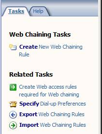
Figure 19
Other than those two options, not much else new is going on with this tab.
The ISP Redundancy Tab
Last but definitely not least is the ISP Redundancy tab. This is new with the TMG firewall, and represents a new TMG firewall feature that allows you to use up to two ISPs with a single TMG firewall or TMG firewall array.
In the Tasks tab of the ISP Redundancy Task Pane, you will see a link for Enable ISP Redundancy. Click that to get started.
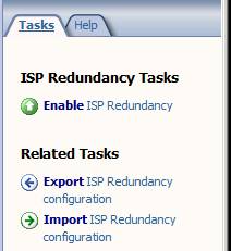
Figure 20
This brings up the Welcome to the ISP Redundancy Configuration Wizard page. Click Next.

Figure 21
On the ISP Redundancy Method page, you have two choices:
- Failover using a primary and backup link – this option allows you to use one ISP link, and if that link goes down, the TMG firewall will switch over to a second ISP. The TMG firewall will continue to check on the status of the primary ISP and when that link comes back online, TMG will switch back to using that one.
- Load balancing between two ISP links – this option allows you to use both ISP connections at the same time, and it automatically balances connections between the two connections, based on the relative weighting you give to each of the links.
In this example we will select the Load balancing between two ISP links option and click Next.

Figure 22
On the ISP Link 1 page there are a number of options:
- ISP Link name – this is where you configure the friendly name for the link.
- ISP Subnet Definition – in this section you configure the IP address of the default gateway used by this link. You can either enter the IP addressing information manually or you can select the NIC that connects to that ISP.
- Explicit Route Destinations – this option allows you to configure routes that will always use this ISP and not use the second ISP. This provides a route based, policy-based routing configuration.
- Link connectivity – gives you three options: Determine automatically, Presume the link is up and Presume the link is down. In most cases you’re going to want the TMG firewall to determine if the link is up or down automatically.
In this example I’ve named the link Verizon and used the Select Adapter option to populate the IP addressing information for the default gateway. Click Next.

Figure 23
On the ISP Link 2 page, you do the same thing, but this time you put in the configuration options for the second ISP connection. In this example, I manually entered the IP addressing information for the default gateway for the Comcast ISP link.
Click Next.

Figure 24
On the Load Balancing Factor page, you set a relative weight for how much you want each of the connections to be used. The default value is to have each of the ISPs used equally.
Click Next.

Figure 25
Check your settings on the Completing the ISP Redundancy Configuration Wizard page and click Finish.

Figure 26
Depending on your configuration and environment, it may take several minutes before you see both ISPs being used, and you might see connectivity stop for clients behind the TMG firewall during this time. Do not worry, be patient. After the configuration becomes active, you will see a graphic indicating the state of the connections. In the example below, it shows that the connection to one of the ISPs is down, as indicated by the red line between the ISP and the cloud.
Also, I have got to hand out props to the TMG team for using a firewall icon in this graphic, instead of the typical Web proxy icon (computer with a tiny firewall icon next to it). It only took ten years, but the message that this product is primarily a firewall seems to be getting out (at least to the product team :))

Figure 27
Note:
You can use the ISP Redundancy feature either by putting multiple IP addresses from different network IDs on the same NIC, or you can dedicate a NIC for each ISP.
I consider it somewhat unfortunate that the TMG team decided to implement the feature in this way, as I suspect most users of this feature will be putting the TMG firewall behind CPE devices provided by their broadband providers, and not connecting the TMG firewall’s NICs directly to each ISP.
It would have been a better design to allow a single NIC or IP address to switch between gateways on the same network ID which would be the IP addresses on the LAN interfaces of the CPE devices, rather than having to create a bogus second network ID to support the second ISP. No, it is not a lot of work, nor is it complicated to implement things to work using the approach they used, but it would have been more elegant to use a “dead gateway detection” like method instead of the approach they use now.
Nevertheless, the feature works well, and failover and failback are smooth and fast.
Summary
In this, the fourth part of our article series on what’s new and improved in the TMG firewall, we covered the options available in the Network node in the left pane of the TMG firewall console. Most significant improvement were the ability to control the source IP address used by the TMG firewall when sending outbound connections, and the new ISP redundancy feature. Next week I hope we’ll be able to finish up by talking about System, Log and Reports, Update Center and Troubleshooting nodes. See you then! –Tom.
If you would like to read the other parts in this article series please go to: