If you would like to read the other parts of this article series please go to:
- Setting Up Failover Clustering for Hyper-V (Part 1)
- Setting Up Failover Clustering for Hyper-V (Part 2)
- Setting Up Failover Clustering for Hyper-V (Part 3)
- Setting Up Failover Clustering for Hyper-V (Part 5)
- Setting Up Failover Clustering for Hyper-V (Part 6)
- Setting Up Failover Clustering for Hyper-V (Part 7)
- Setting Up Failover Clustering for Hyper-V (Part 8)
- Setting Up Failover Clustering for Hyper-V (Part 9)
Introduction
In the previous article, I showed you how to configure Windows Storage Server 2008 to act as an iSCSI target. We will eventually use this iSCSI target as a shared storage pool for our Hyper-V cluster. Before we can do that though, we have to connect the servers that will eventually act as our cluster nodes to the iSCSI target that we have created. In this article, I will show you how it’s done.
Before I Begin
Before I get started, I want to take a moment and explain that if you have followed the instructions from my previous article then establishing a connection between an iSCSI initiator and an iSCSI target should be effortless. Having said that, there is one issue that you could potentially run into.
Normally when you run the iSCSI initiator for the first time it will ask you two questions. The first question is whether or not you want to run the iSCSI Service automatically. The second question is whether or not you want to allow iSCSI traffic through the Windows firewall.
It doesn’t take a rocket scientist to know that you need to answer Yes to both questions. The problem is that while I was writing this article series, I set up iSCSI connectivity several times so that I could make sure that my procedures were correct. In doing so, I discovered that Windows would occasionally omit one or both of these questions. If that happens then you will need to manually enable the iSCSI Service and configure your firewall to allow iSCSI traffic to flow through port 3260. If you have any hardware firewalls between the storage server and the cluster nodes then you will need to allow iSCSI traffic to pass through them as well. Unless the iSCSI Service is running and iSCSI traffic can traverse your firewalls then what I’m about to show you won’t work.
Connecting the First Cluster Node
Even though we have set up the iSCSI initiators and the iSCSI target in the previous article, they aren’t quite ready to use for our failover cluster. We still need to mount our shared storage pool in a way that allows the cluster nodes to use it. I’ll start out by showing you how to connect the first cluster node.
On your first cluster node, open the iSCSI Initiator and go to the Targets tab. Click the Refresh button and you should see your iSCSI target displayed among the list of discovered targets, as shown in Figure A.
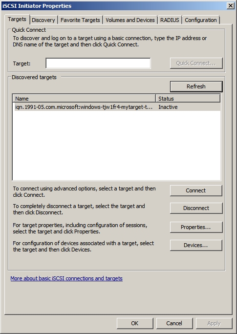
Figure A: Your iSCSI target should be displayed in the list of discovered targets.
As you look at the figure above, you will notice that the target’s status is listed as Inactive. To correct this, select the target and click on the Connect button. When you do, Windows will display the Connect to Target dialog box, shown in Figure B. Make sure that the Add This Connection to the List of Favorite Targets check box is selected, and click OK.
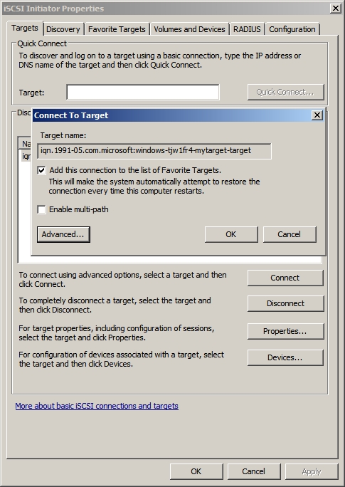
Figure B: Select the Add This Connection to the List of Favorite Targets check box.
At this point, the target’s status should change to Connected, as shown in Figure C.

Figure C: The Target’s status should be Connected.
Now that we have connected our cluster node to the target, we have to prepare the target for use. To do so, enter the DISKMGMT.MSC command at the server’s Run prompt. When you do, Windows will open the Disk Management Console.
The target that you have just connected should be displayed within the Disk Management console as an unknown disk. Right click on the disk (not the unallocated space within the disk) and choose the Online command from the shortcut menu, as shown in Figure D.

Figure D: Right click on the target disk and choose the Online command from the shortcut menu.
After you bring the disk online you must initialize it. Simply right click on the disk as you did a moment ago, but this time select the Initialize Disk command from the shortcut menu, as shown in Figure E.
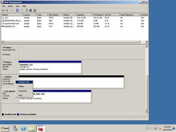
Figure E: Right click on the disk and choose the Initialize Disk command from the shortcut menu.
Windows will now ask you to verify the identity of the disk that you want to initialize. You will also be asked if you would like to use MBR partitions or GPT partitions, as shown in Figure F. If the shared disk (or actually the virtual hard drive shared by the target) is greater than 2 TB in size then you will need to use GPT partitions. Just be aware that older versions of Windows may not be able to directly connect to it. Of course this shouldn’t be a problem since only cluster nodes should be connecting to the disk.
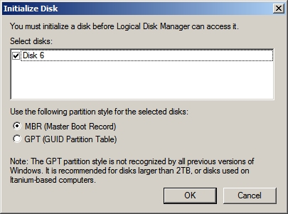
Figure F: Windows asks if you want to use MBR or GPT partitions.
Now the cluster node can use the iSCSI target as if it were a locally attached disk. As such, the first thing that you will need to do is to create a volume on it. To do so, right click on the unallocated space and then choose the New Simple Volume command from the shortcut menu, as shown in Figure G.

Figure G: Create a new volume on the disk.
Windows will now launch the New Simple Volume Wizard. Click Next to bypass the wizard’s Welcome screen. You should now see a screen asking you how large you want to make the new volume.
Choosing a size for the volume can be tricky. Remember that the volume will store one or more virtual hard drives for your Hyper-V cluster nodes. You must also remember that you are technically creating a volume on a virtual hard drive, which means that you will have virtual hard drives within a virtual hard drive. As you consider how large to make the volume, consider how many virtual hard drives you want to store within the volume that you are creating and what the space requirements for those virtual hard drives will be.
After you determine the appropriate size of the volume, click Next and Windows will ask you to assign a drive letter to the volume. You can use any drive letter that you want, but for the sake of consistency it’s a good idea to use the same drive letter on each of the cluster nodes.
Click Next and you will be prompted to format the volume. After setting your formatting options, click Next, followed by Finish to complete the process. The disk is now ready to use.
If you look at Disk 6 in Figure H, you will see that it appears as if it is a local disk using Direct Attached Storage. There is no indication that the disk actually exists on an iSCSI target.
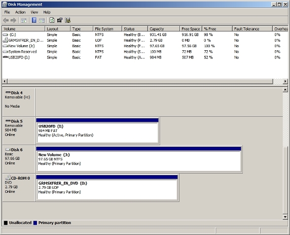
Figure H: The disk looks as though it is locally attached.
The storage volume is accessible through Windows Explorer in exactly the same way as any other volume would be. If you look at Figure I, you can see that you would be hard pressed to tell that this is an iSCSI volume.

Figure I: The shared storage pool is accessible through Windows Explorer.
Conclusion
In this article, I showed you how to connect the first cluster node to the iSCSI storage pool. In Part 5, we will connect the remaining cluster nodes to our storage pool.
If you would like to read the other parts of this article series please go to:
- Setting Up Failover Clustering for Hyper-V (Part 1)
- Setting Up Failover Clustering for Hyper-V (Part 2)
- Setting Up Failover Clustering for Hyper-V (Part 3)
- Setting Up Failover Clustering for Hyper-V (Part 5)
- Setting Up Failover Clustering for Hyper-V (Part 6)
- Setting Up Failover Clustering for Hyper-V (Part 7)
- Setting Up Failover Clustering for Hyper-V (Part 8)
- Setting Up Failover Clustering for Hyper-V (Part 9)