If you would like to read the first part in this article series please go to Kicking the Tires on the TMG 2010 RC ISP Redundancy – Part 1: Configuring the Virtual Infrastructure and the TMG Firewall Interfaces.

Introduction
In the first part of this article series, we went over the lab network and what you need to do with the interfaces to get them ready for multi-ISP support. Now that we have got the basic groundwork covered, let us get to the fun part!
To start, open the TMG firewall console and click the Networking node in the left pane of the console. In the Task Pane, click the Tasks Tab. On the Tasks Tab, click the Configure ISP Redundancy link, as seen in the figure below.
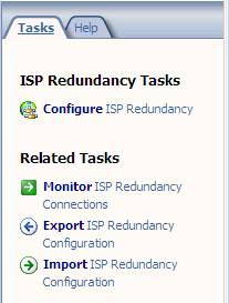
Figure 1
This brings up the Welcome to the ISP Redundancy Configuration Wizard page. Click Next.
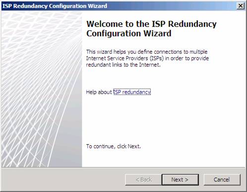
Figure 2
On the ISP Redundancy Mode page, you can choose one of two options:
-
Load balancing with failover capability. This option allows you to use both ISPs at the same time. You can set a preferred ISP where most of the traffic goes out of the preferred ISP, or you can have traffic use both ISPs equally. Use this option if you want to get more total bandwidth and don’t have to worry about paying for bandwidth for both ISPs. If one of the ISPs fails, all traffic will go out the other ISP connection.
-
Failover only. Use this option if you only want to use a single ISP, but want the other to be used if the first ISP fails. Use this option if you don’t want to pay for bandwidth for both ISPs, but want to make sure that you can stay online if the primary ISP fails. This is a good option if you have to pay bandwidth charges for the second ISP.
In this example we’ll choose the Load balancing with failover capability option. Click Next.
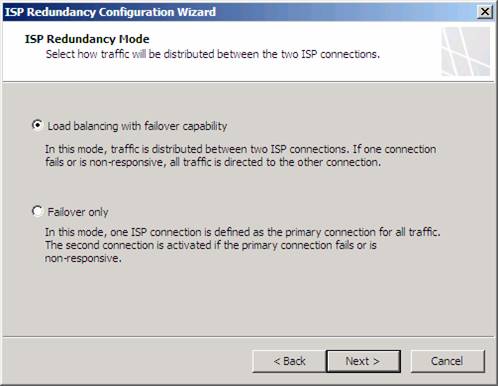
Figure 3
On the ISP Connection 1 page you configure the settings for the first ISP link. In this example, we will name the connection RRAS1, since this will be the connection through the RRAS1 NAT server that’s simulating the first ISP. Since we are using separate NICs for each of the ISP connections, we can select the NIC that connects us to RRAS1 in the Network adapter (optional) drop down list. Notice that after we select the NIC, the subnet address that defines the default gateway for that NIC, which is the internal address of the RRAS1 NAT server, is listed in the Subnet text box. Remember, each ISP must be on a different network ID, which means that each ISP connection is on a different subnet.
Click Next.
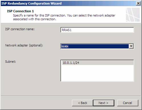
Figure 4
On the ISP Connection 1 – Configuration page, confirm the Gateway address and Mask. Also confirm the Subnet text box has the correct subnet mask. You can enter a Primary DNS server and a Alternate DNS server if you like, but since it is highly recommended that you do not configure the firewall to use external DNS servers, I suggest that you never enter any addresses in these text boxes. There will be times when you need to enter external IP address for DNS servers on the TMG firewall, but this is not one of them.
Click Next.
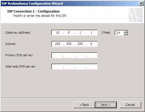
Figure 5
On the ISP Connection 1 – Dedicated Servers page, you enter the IP addresses of servers that you always want to always use this ISP connection. These are typically servers that are on the ISP’s network that aren’t accessible from outside networks, such as DNS and time servers. SMTP servers are also often placed on the ISP network for outbound messages that are not available from outside networks. Since we are not using forwarders in this example, and we are using Internet time servers, we would not enter any IP addresses for the dedicated servers.
Note that if you do enter IP addresses for dedicated servers, if that ISP goes down, the connections won’t be forwarded out the other ISP. However, this should not be much of an issue, since these IP addresses would not be accessible from external networks anyway.
Click Next.
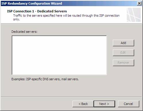
Figure 6
On the ISP Connection 2 page, you do the same thing you did on a similar page for ISP 1. In this example, ISP2 is going to be the one that connects through the RRAS2 NAT server. Note that the Subnet is on a different network ID than the first ISP connection.
Click Next.
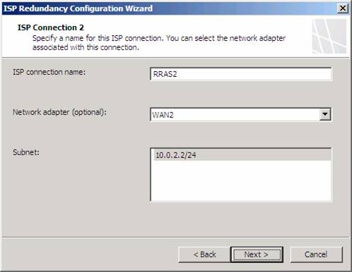
Figure 7
Confirm the settings on the ISP Connection 2 – Configuration page and click Next.

Figure 8
On the ISP Connection 2 – Dedicated Servers page, you enter the IP addresses of servers that are accessible from the second ISP connection. The same principles and limitations apply here as they did with the first ISP connection.
Click Next.
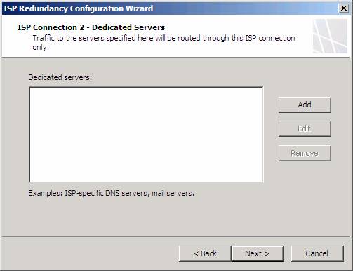
Figure 9
On the Load Balancing Configuration page, you decide how you want to weigh the connections. If the connections are the same speed, you typically will set it up to use both ISPs equally. However, if one ISP is faster than the other, you will want to give me weight to the faster ISP. In this example, RRAS2 is faster than RRAS1, so I will give it 75% of the connections and RRAS1 25% of the connections. Connections are based on the method I described in the first paper of this series, so if you want to know how the TMG firewall assigns connections, check out part 1 of this series.
Click Next.
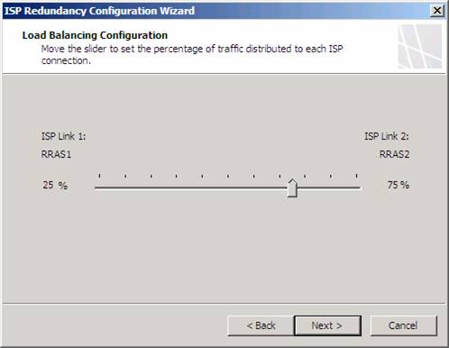
Figure 10
Check your settings on the Completing the ISP Redundancy Configuration Wizard page, and then click Finish.
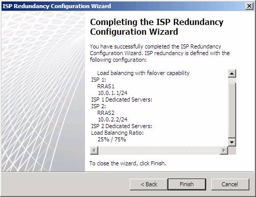
Figure 11
After you click Finish a dialog box appears informing you that you must add a persistent static route for each DNS IP address configured on the external network adapters on every Forefront TMG server. This is required to ensure that DNS requests are routed through the proper network adapter.
The reason you need to manually create static routes for the ISPs is that the automatic routing that works with ISP Redundancy only works when there is a NAT relationship between source and destination. Since the DNS connections are coming from the TMG firewall itself, the connection is going to have a route relationship, since all connections from the Local Host Network to any other network use a route relationship.
Click OK.
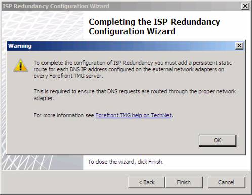
Figure 12
Click Apply to save the firewall configuration. Enter a change description in the Configuration Change Description dialog box if you like, then click Apply in that dialog box. Click OK in the Saving Configuration Changes dialog box.
Now let’s take a look at how some of the ISP Redundancy feature works. First, let us take a look at the Dashboard. Here you can see information about Network Status for the ISP connections. In the figure below, you can see the Status, the Uptime and the Bytes/Sec being used by each ISP. Notice that RRAS2 is using a lot of bandwidth because at the time I took the screenshot, I was downloading Windows XP SP2 through the TMG firewall.
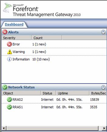
Figure 13
What if you want to change the configuration of the ISP Redundancy settings? Just click on the Networking node in the left pane of the TMG firewall console and double click on the ISP connection you want to change. In the figure below, you can see the General tab of the RRAS1 Properties dialog box. Here you can change the Name, Gateway IP address, Mask, Subnet, Connectivity detection, and Load Balancing ratio.
Notice that the Connectivity detection option was not exposed in the wizard. Here you have three options:
-
Disable, connection is down. This disables detection of whether the ISP is up or down and disables the ISP connection. You might want to set this if you want to disable this ISP for a while for administrative or testing purposes.
-
Disabled, connection is up. This disables detection of whether the ISP is up or down but leaves the link up. Again, you might want to enable this option if you want the ISP connection to be used all the time, regardless of the status of the link.
-
Enabled. This is the default setting.
Now you might wonder “how does the TMG firewall detect whether an ISP link is up or down?” That’s a good question. What TMG does is send connection requests to the root DNS servers on the Internet. If it connects, then the connection is up – if it does not connect, then the connection is down.

Figure 14
We can confirm this by looking a piece of a NetMon trace in the figure below. IP addresses 10.0.2.3 and 10.0.1.3 are the external addresses on the TMG firewall connecting to each of the ISP connections. The destination address 192.33.4.12 is an IP address of one of the root DNS servers on the Internet. What’s interesting here is that these are not actually DNS queries – they are just TCP port 53 connections to the root DNS servers. If you look at the decode, you will find that there is no DNS protocol information. You only see a three-way handshake. I’m sure there’s a good reason for this, but I do not know what it is.
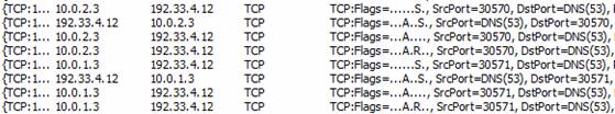
Figure 15
Now, how does the TMG firewall decide that a connection is down, and how does it decide that the connection is up again?
Multiple servers are polled to determine if there are any connectivity problems through a particular ISP. If multiple Root DNS servers fail to respond through a specific ISP, TMG retries the connection two more times (for three total attempts, which includes the first one) at an interval of 60 seconds each before switching over to the secondary ISP connection and marking the other connection as “down”.
So, if RRAS1 actually went down at 12:58PM, it will check connectivity to the root DNS servers at 12:59PM and 1:00PM. If both connection attempts fail, then the link is marked “down”. During the period between 12:58PM to 1:00PM, connections will still be routed through the dead ISP.
After the ISP connection is marked “down”, the TMG firewall will test the “downed” ISP every 5 minutes (300 seconds) and when the “downed” connection responds for the first time, two more consecutive requests at an interval of 60 seconds each must be successful before the primary link is marked as working again. Once the primary link is considered operational, TMG creates new connections using the primary ISP link.
So, if RRAS1 was marked “down” at 1:00PM, it won’t be tested again until 1:05PM. Then a test at 1:05PM is done. If successful, it will test again at 1:06PM and again at 1:07PM. If both of those tests are successful, then the link will be marked “up” and connections will be routed through that connection again.
To see what happens when an ISP goes down, I turned off RRAS2. If you wait 2-3 minutes, you’ll see in the Dashboard node in the left pane of the TMG firewall console, so that Status changes to Local.
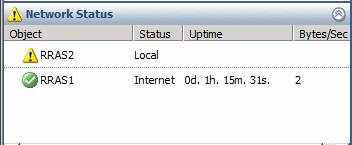
Figure 16
However, there is no problem! I went to my client and downloaded a file and it automatically move to RRAS1. Keep in mind that if the client was using the downed ISP to reach a particular site, it’s going to take about 2 minutes before that site is routed to the online ISP.
If you check the Alerts, you’ll see one generated that informs you that the ISP connection is unavailable, as seen in the figure below.
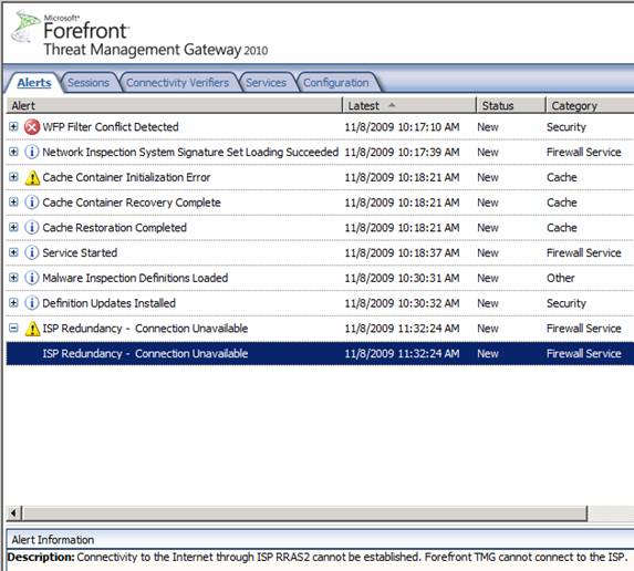
Figure 17
Speaking of alerts, there are several of them related to ISP Redundancy, as seen in the figure below.
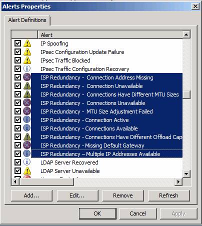
Figure 18
Summary
In this two part series I went through how ISP Redundancy works, how to set up your NICs to prepare for ISP Redundancy, and how to configure the feature. Note that this article series referred to a specific use case, where you have a dedicated NIC for each ISP. This is not a requirement. You can put both ISP IP and gateway addresses on a single NIC. If anyone is interested, I can do a separate article on that configuration, but it’s pretty straightforward and the same principles apply. Have fun with TMG ISP Redundancy and let me know what you think of it and how it works for you! Thanks! –Tom.
If you would like to read the first part in this article series please go to Kicking the Tires on the TMG 2010 RC ISP Redundancy – Part 1: Configuring the Virtual Infrastructure and the TMG Firewall Interfaces.