If you would like to read the other parts in this article series please go to:
- Test Lab Guide: Demonstrate Site to Site VPN with Threat Management Gateway 2010 (Part 1)
- Test Lab Guide: Demonstrate Site to Site VPN with Threat Management Gateway 2010 (Part 2)
- Test Lab Guide: Demonstrate Site to Site VPN with Threat Management Gateway 2010 (Part 3)
Introduction
Thanks for joining us again as we go through this Test Lab Guide on creating a site to site VPN using the TMG firewall. In the previous parts of this four part series, we already installed and configured key services on the branch office subnet to support the TMG VPN site to site VPN gateway. We also installed the TMG firewall on the branch office TMG firewall machine. At this point, we are ready to configure the remote site network for the site to site VPN connection. Let’s get started!
In the left pane of the TMG firewall console, click the Remote Access Policy (VPN) node and then click the Tasks Tab in the Task Pane. Next, click on the Create VPN Site-to-Site Connection link, which is shown in Figure 1 below.

Figure 1
Now, on the Welcome to the Create VPN Site-to-Site Connection Wizard page, we start by naming the network. Enter Main in the Site-to-site network name text box that you can see in Figure 2. Click Next.

Figure 2
On the VPN Protocol page, which you see in Figure 3, we’re asked to choose the VPN protocol that we want to use to encrypt the traffic sent between our two sites. We have the choices of IPsec tunnel mode, L2TP over IPsec, or PPTP. For this Test Lab Guide, select the Layer Two Tunneling Protocol (L2TP) over IPsec. We need to select this option here because the protocol has to be the same on both sides of the connection, and we already selected L2TP/IPsec at the main office TMG firewall when we set it up last time. If you needed interoperability with third party vendors, you would select the first option. Click Next.

Figure 3
Note that a dialog box appears after you click Next, which informs you that you need to create a user account that the main office TMG firewall can use to authenticate with the branch office TMG firewall. The procedure is the same as that we used when we were configuring the main office TMG firewall. Click OK to dismiss the dialog box that’s shown in Figure 4.

Figure 4
In the Local Network VPN Settings page, which you can see in Figure 5, we need to define how the VPN clients will get IP addresses. Select the Dynamic Host Configuration Protocol (DHCP) option. We can use this option because we installed a DHCP server at the branch office. When you select this option, the TMG firewall will request 10 IP addresses from the DHCP scope that it can use to assign its VPN interface an IP address and to assign IP addresses to the VPN clients and the main office VPN gateway. Click Next.

Figure 5
On the Remote Site Gateway page that’s shown in Figure 6, we have to tell TMG the IP address or the fully qualified domain name of the remote VPN server. Enter 131.107.0.2 in the Remote site VPN server text box, then click Next.

Figure 6
On the Remote Authentication page that you can see in Figure 7, we have to let TMG know which user account on the remote site to use for authentication. Put a checkmark in the Allow the local site to initiate connections to the remote site, using this user account. Then enter the user credentials. This is the same user account that you created on the main office TMG firewall in the previous installment of this series. In case you’ve forgotten it, in the user name text box, enter Branch; in the Domain text box, enter TMG1; in the Password text box, enter p@ssword1; in the Confirm password text box, enter p@ssword1. Click Next.

Figure 7
On the L2TP/IPsec Outgoing Authentication page, shown in Figure 8, we have to pick the authentication method that will be used to connect to the remote site. Certificate authentication is recommended because it’s more secure, but for purposes of this Test Lab Guide, we’ll select the Pre-shared key authentication option (because it doesn’t require a PKI) and then in the Pre-shared key text, enter 123456789. Click Next.

Figure 8
On the Incoming L2TP/IPsec Authentication page that you can see in Figure 9, we choose the authentication method to be used for the incoming L2TP/IPsec connections. This typically is the same as that used for outgoing connections, so select the Allow pre-shared key authentication for incoming L2TP connections option. In the Pre-shared key text box, enter 123456789

Figure 9
On the Network Addresses page that’s shown in Figure 10, we’ll add the IP address ranges of the remote site, which should be the same as those on the other end. Click the Add Range button. In the IP Address Range Properties dialog box, in the Start address text box, enter 10.0.0.0. In the End address text box, enter 10.0.0.255 and then click OK.
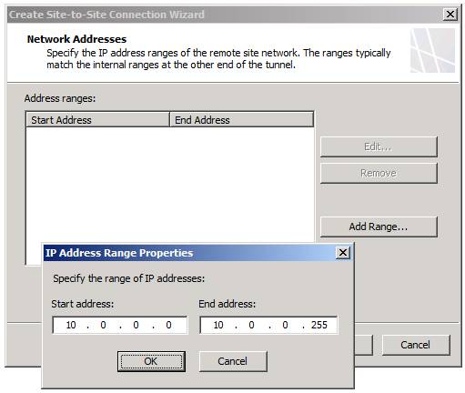
Figure 10
Okay, now you can see the addresses that define the remote site network (which is the address range used at the main office) in the Address ranges list that’s shown in the dialog box in Figure 11. Click Next.

Figure 11
On the Remote NLB page that you see in Figure 12, we want to remove the checkmark from the The remote site is enabled for Network Load Balancing checkbox for this Test Lab Guide, since we aren’t enabling NLB on the remote site. Then click Next.

Figure 12
On the Site-to-Site Network Rule page that you see in Figure 13, we’re going to create a network rule that will allow traffic to be routed to and from the new VPN site to site network. Go ahead and accept the default name for the Network Rule, which in this case is Main to Internal Network. This rule will create a Route relationship between the main office and the branch office networks. Click Next.

Figure 13
On the Site-to-Site Network Access Rule page that you can see in Figure 14, select the Create an allow access rule. This rule will allow traffic between the Internal network and the new site-to-site network for all users. Accept the default name for the rule, which is Allow access between Main and Internal. In the Apply the rule to these protocols drop down box, select the All outbound traffic option. Then click Next.

Figure 14
On the Completing the New VPN Site-to-Site Network Wizard page that’s shown in Figure 15, click Finish.

Figure 15
Next, click OK in the dialog box shown in Figure 16, which informs you that you need to create the user account that the main office TMG firewall will use to authenticate with the branch office TMG firewall.

Figure 16
Don’t forget to click Apply in the middle pane of the TMG firewall console to save the changes to the firewall policy, as shown in Figure 17.

Figure 17
Wait! We aren’t quite finished yet. In the Server Manager of the branch office TMG firewall, we need to create a new user account named Main, as shown in Figure 18.Give that account the password of p@ssword1. Remove the checkmark from the User must change password at next logon checkbox. Put a checkmark in the User cannot change password and Password never expires checkboxes. Click OK.

Figure 18
Double click on the Main account and in the Main Properties dialog box that you can see in Figure 19, click the Dial-in tab. On the Dial-in tab, select the Allow access option in the Network Access Permission frame. Then click OK.

Figure 19
We’re almost there so hang in there with us. Now go to the BRANCHSVR1 computer and open a command prompt. In the command prompt window, enter ping 10.0.0.1 and press ENTER. This will start the site to site VPN connection. Note that you will not receive a reply from the main office DC1 computer because the Windows Firewall will not allow pings from off-subnet hosts. However, it will start the VPN connection.
Click the Monitoring node in the left pane of the TMG firewall console as shown in Figure 20. Then click the Sessions tab. Here you can see that the TMG firewall as established a VPN Remote Site connection and that it is using L2TP/IPsec.

Figure 20
Summary
There you have it! In this, part 4 (and the final part) of the TMG site to site VPN Test Lab Guide series, we walked through the steps of creating a site to site VPN between two TMG firewalls using the L2TP/IPsec VPN protocol, building on all the work we did in Parts 1 through 3. After completing the configuration, we tested it to determine that the site to site connection would actually be established and we confirmed the functionality by checking the Sessions tab in the Monitoring node. Now we have a functioning site to site VPN connection between the VPN gateways on our main office TMG firewall and our branch office TMG firewall, which can be used to provide a secure connection between the two locations.
If you would like to read the other parts in this article series please go to: