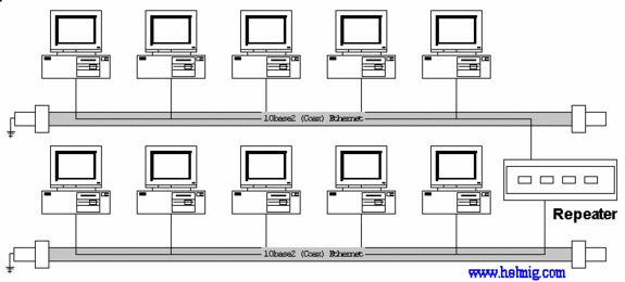
Networks have the trend to grow, requiring often the need for repeaters ( on 10base2 – Thin-Ethernet ) or multiple hubs (on 10/100baseT Twisted-Pair), where it is required to follow the rules on maximum number of Repeaters/Hubs ( Large Networks: 5-4-3 Rule ).
This includes today also the possibility to connect systems without cables using a
WLAN AccessPoint.
10base2 – Thin Ethernet (Coax):
10baseT – Twisted Pair (TP/UTP):
But these ‘cable-extension‘ method have all a serious limitation
concerning the maximum throughput of the network:
(explanation is visually via the animated GIF below)
Hubs and repeaters are fairly simple, ‘non-intelligent‘ devices:
whatever comes in on one port, gets amplified and send out to ALL other ports, so any network transmission ‘fills up/flows into‘ ALL cable-segments of the network, so only ONE network connection can be active at a time on the complete network !
When multiple system try to communicate at the same time:
(explanation is visually via the animated GIF below)
then the signals ‘collide’/corrupt each other, making them invalid, time has been wasted and the system will try after a random delay again to transmit, resulting in network slowdown.
There is a possibility to optimize such network configurations:
Bridge:
In the early days of networking, such a ‘intelligent‘ device called ‘Bridge‘ viewed at the data inside the transmissions, to find out based on the Network-card addresses (MAC), whether it is necessary to transmit the information to a different segment or not. Such Bridges has only 2 connectors, allowing to split large networks into 2 smaller sub-networks.
Switch:
Switches are also ‘intelligent‘, but are able to handle more than 2 ports and are able to handle more than 2 communications at the same time:
When a transmission comes in on one port, the switch looks at the MAC addresses to determine, onto which port to send it out:
Now a large network can handle MULTIPLE transmissions at the same time:
(explanation is visually via the animated GIF below)
But to be able to get this additional Through-put, careful planing of the network layout is required, looking on the flow of the network traffic:
Singe Server configuration:
Swapping a hub to a Switch in such a configuration will not optimize the network, since the connection from the TP-HUB to the server is still the bottle-neck.
Multi Server configuration:
If most the network traffic is within the workgroups (departments,..) and only few network traffic is between the workgroups, then a Switch is the solution to optimize network utilization.
Optimize 10 Mbit Network using a 100 MBit Server connection:
Blackbox = Hub
if the ‘Blackbox‘ is a hub (even if it is a switching 10/100 Mbit hub), the throughput of the complete network is limited at 10 Mbit (since ALL traffic is transmitted by a hub to ALL connected segmentsand even a 100 Mbit connection
from the hub to the server results to a very limited improvement ):
Blackbox = Switch
if the ‘Blackbox‘ is a Switch, then each connected system can communicate at full speed of the 10 Mbit with the server ( because the switch does NOT pass it through to the other 10 MBit segments and the connection of 100 MBit with the server can handle the higher throughput)
In reality, a server is handling multiple network requests at the same time,
which makes the use of a Switch and a 100 Mbit link between the switch and
the server even more efficient: 
Since changing of 10 MBit TP-cabling to 100 Mbit/CAT5-cabling is expensive
in offices (where cables run inside walls and across sealings), swapping a
10 Mbit HUB to a 10/100 MBit SWITCH and upgrading the connection to the
server to 100 Mbit is a cost-effective solution to improve network throughput.


